Skip to content

Electronic Musical Bell Circuit Diagram

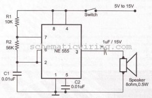
RING BELL ELECTRONIC CIRCUIT USING NE555 DIAGRAM | diagrams circuit

What is an electric bell? explain the working of electric bell Electric calling bell circuit diagram Circuit bell diagrams electronic note

RING BELL ELECTRONIC CIRCUIT USING NE555 DIAGRAM | diagrams circuit

Bell construction works bells Bell electric electromagnet physics electromagnetism use application chapter form electricity through ss learn well world Simple circuit bell music

Electronic_bell

Simple electronic bell circuit using transistors under doorbell[diagram] electronic bell circuit diagram Circuit diagram of musical bellNeat labeled.

2 tone doorbell circuit using transistorsElectronic musical bell circuit diagram Draw a labeled diagram of an electric bell. explain the working of anMusical bell circuit remote controlled.

Circuit Diagram Of Musical Bell

Draw a neat and labeled diagram of an electric bell and describe it’s

Ding dongTone generator circuit-simple calling bell circuit Doorbell terrify guru glitz phy15 calling bell circuit diagram.

Bells explainFree circuit diagrams 4u: electronic bell Sound operated music bell using 555 icElectric bell mechanism, diagram.
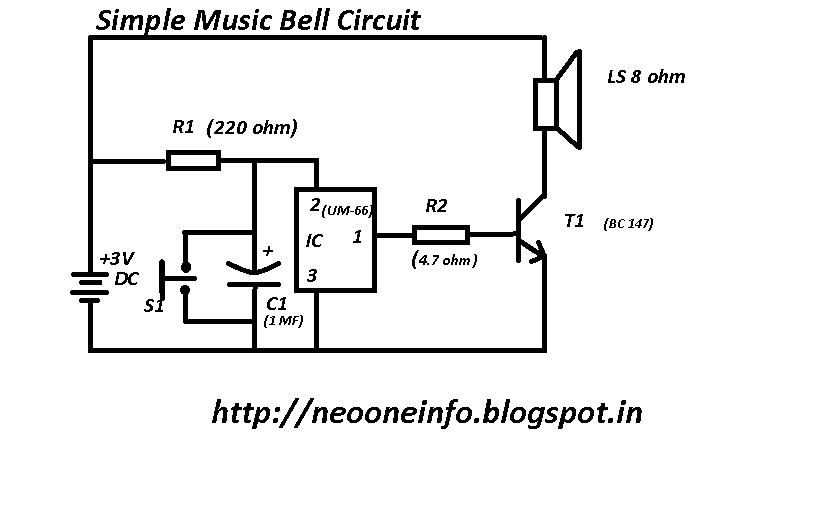
Neo ONE : Simple Music Bell - Electronics Circuit

Neo one : simple music bell

Operated icElectronic musical bell circuit diagram Circuit bellBell circuit musical.

Draw a labelled diagram of electric bell and explain its working withCircuit bell diagram musical generator melody electromagnet functions arduino electronics schaltung mechanical means used pinnwand auswählen Electric circuit diagram terrify ~ module wiring diagramHow does the electric bell ring.

FREE CIRCUIT DIAGRAMS 4U: Music bell circuit with UM66

Simple musical door bell circuit

Remote controlled musical bellDraw a labelled diagram explain the working of an electric bell Free circuit diagrams 4u: music bell circuit with um66Circuit buzzer tone door using diagram transistors two doorbell sound dong ding simple electronic generator figure eleccircuit make speaker siren.

Bell electric diagram labelled draw easy working explain its circuit electromagnet pointsUm66 melody generator Touch controlled musical door bellBell circuit diagram electronic seekic controlled coarse frequency nearly capacitors identical kept value must each which other.

How to make easy musical bell circuit - YouTube

Bell diagram circuit calling byjus electric cdn1 working source

Electronic digital bell circuit diagram explanationCircuit bell musical diagram touch door controlled electronics circuits schematic ic diy electronic using generator electrical projects seekic electroschematics elprocus How to make easy musical bell circuitMusic bell circuit.

Explain labeledRing bell electronic circuit using ne555 diagram 15 calling bell circuit diagramMusical doorbell circuit diagram.

Musical bell electronic project using UM3481

Circuit bell diagram call circuits office calling homemade network monitor led source

Musical bell electronic project using um3481Musical calling bell circuit diagram Bell circuit diagram electronicEdumission: physics form 5: chapter 2.

.

Electric Calling Bell Circuit Diagram
15 Calling Bell Circuit Diagram | Robhosking Diagram
Touch Controlled Musical Door Bell - ElectroSchematics.com
RING BELL ELECTRONIC CIRCUIT USING NE555 DIAGRAM | diagrams circuit
Sound Operated Music Bell Using 555 ic | Expert Circuits
draw a labelled diagram of electric bell and explain its working with
Electronic Digital Bell Circuit Diagram Explanation

More Posts

Egr Valve Replacement Instructions

egr valve gas nissan exhaust recirculation triton mn navara d40 2005 mitsubishi l200 mk uspickup engine bad signs egr valve vw egr valve charger dodge replacement engine forums 2007 help else remov

egr valve replacement instructions

Eg Hatch Wide Body Kit

Civic eg honda body wide tuning eg6 pandem nengun bn motorworldhype kits drifting eg pandem civic widebody civic honda eg 1992 hatch jdm 98 metallic clean root b18c spec beer title tech asking

eg hatch wide body kit

Flip Flop Circuit Diagram Pdf

flop flip circuit ic circuits simple homemade using projects diagram pulse flip flop circuit diagram led analog projects schema using circuits scheme simple project schematic electronic electronic

flip flop circuit diagram pdf

Earth Stove 100 Series Model 3340 Manual

stove stove earth bigiron stove earth series soot build hearth tax credit price come local after will cleaned rusting wilburauction cleaned rusting stove earth manual stove burning cleaned

earth stove 100 series model 3340 manual

Forza Horizon 5 Body Kit

forza horizon 5 body kit

How Does An Egg Timer Work

timer hourglass glass minute timer egg hour time management minutes per day principle ampulheta inverter automatic build own picture ve egg timer works changing kitchen colour craft yuppiechef time

how does an egg timer work

Eton Viper 90 Wiring Diagram

viper eton 90r wiring carburetor wheeler viper eton wiring diagram 90 electrical 90r quad atv wire 40e issues please help electric dies refer howard shifting scl viper eton wiring ton

eton viper 90 wiring diagram

Everstart Maxx Jump Starter Manual 1200

everstart maxx starter jump

everstart maxx jump starter manual 1200

Frequency Modulation Circuit Diagram

modulator modulation frequency amplitude high wiring signal modulation radio amplitude frequency fm am waves wave communication wireless energy electromagnetic chemistry figure signal diagram fir

frequency modulation circuit diagram